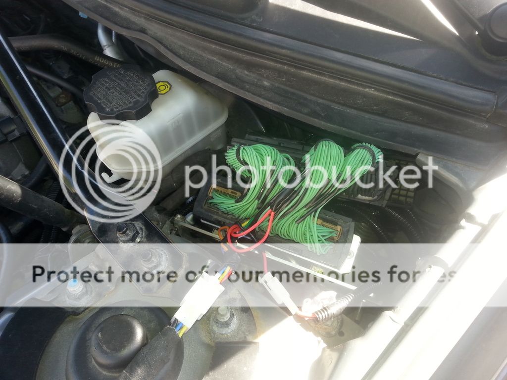
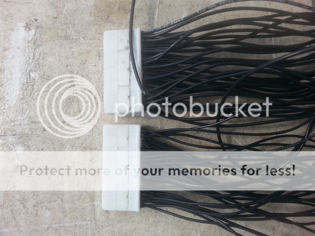
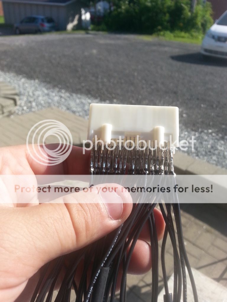
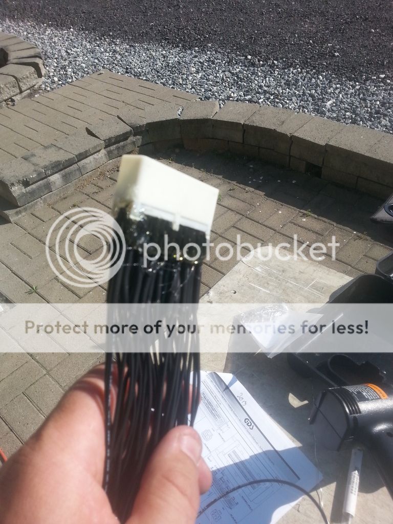
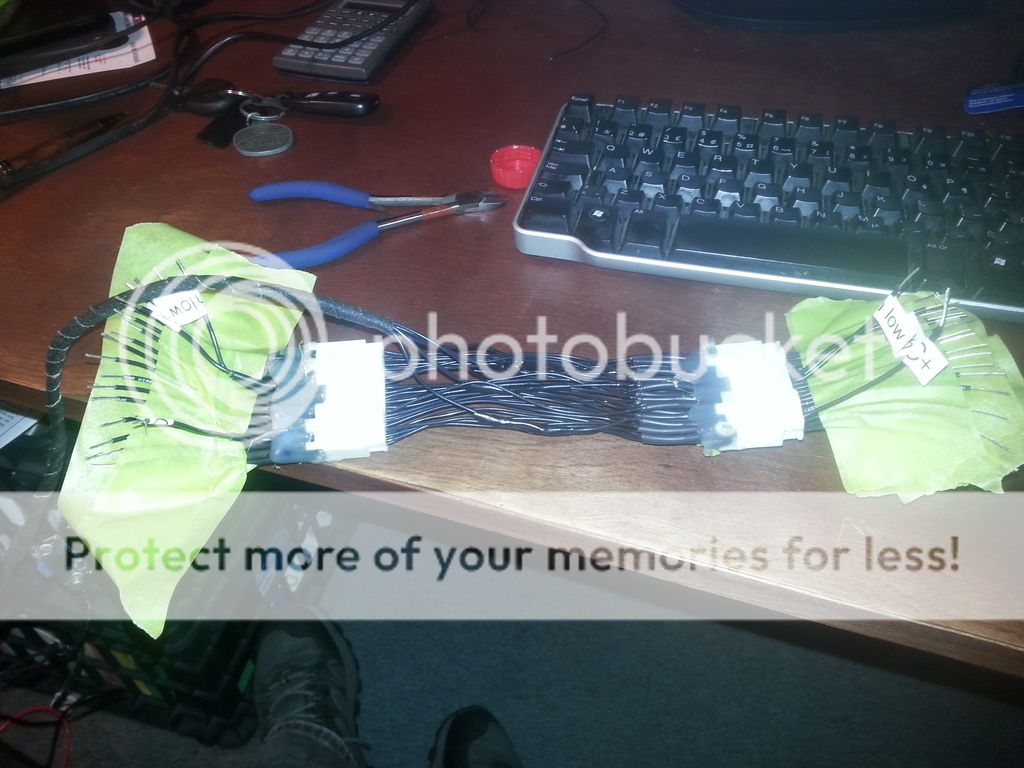
go crazy a do a testing harness lol
i had my first harness so i cut it in half and did some testing with it lol...not neccessary for only one
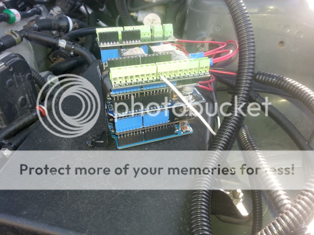
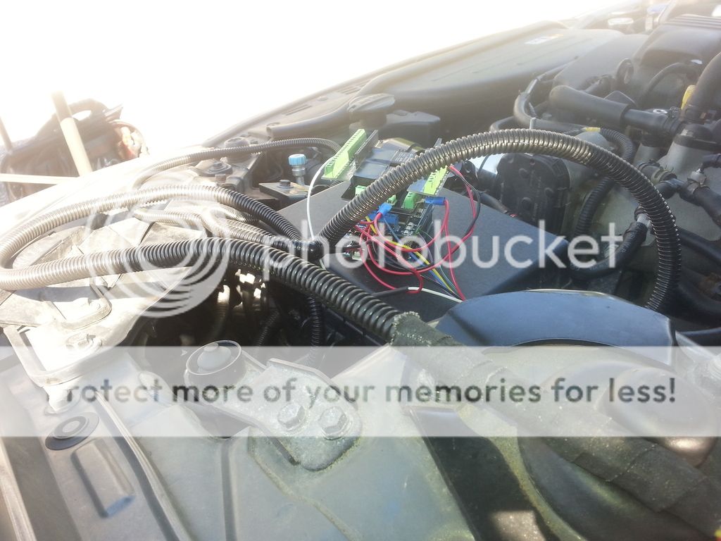
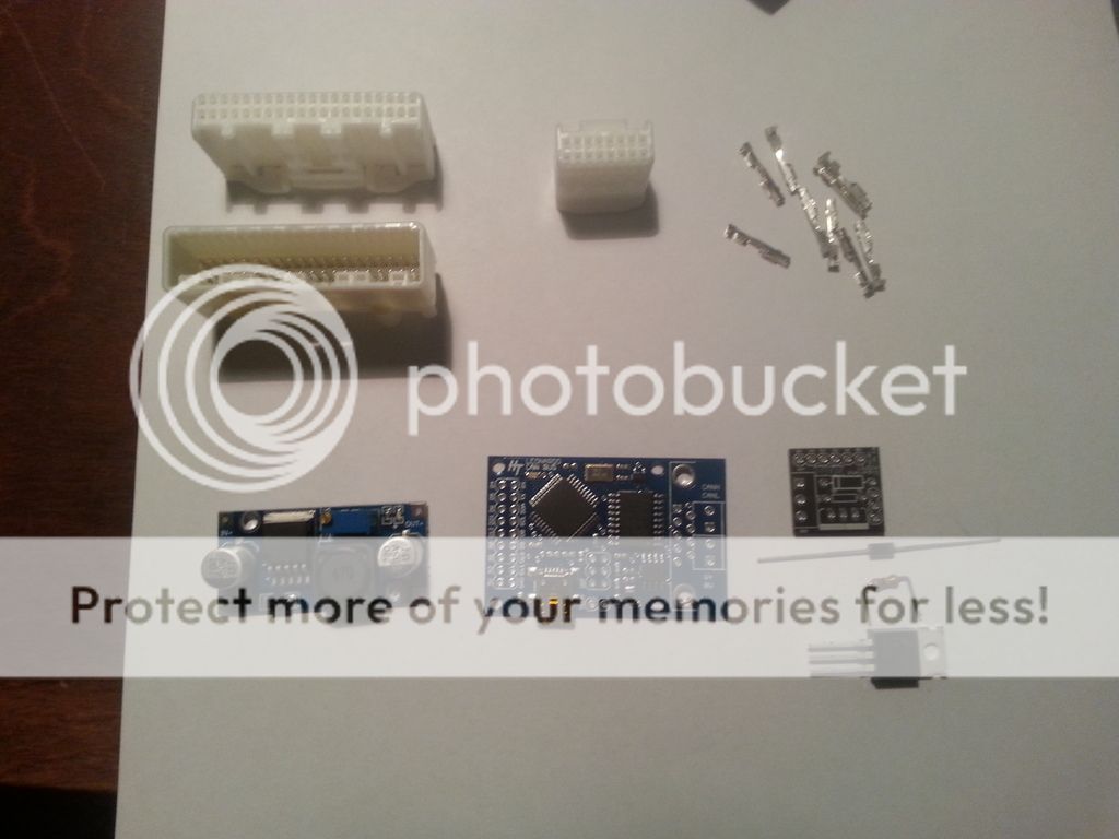
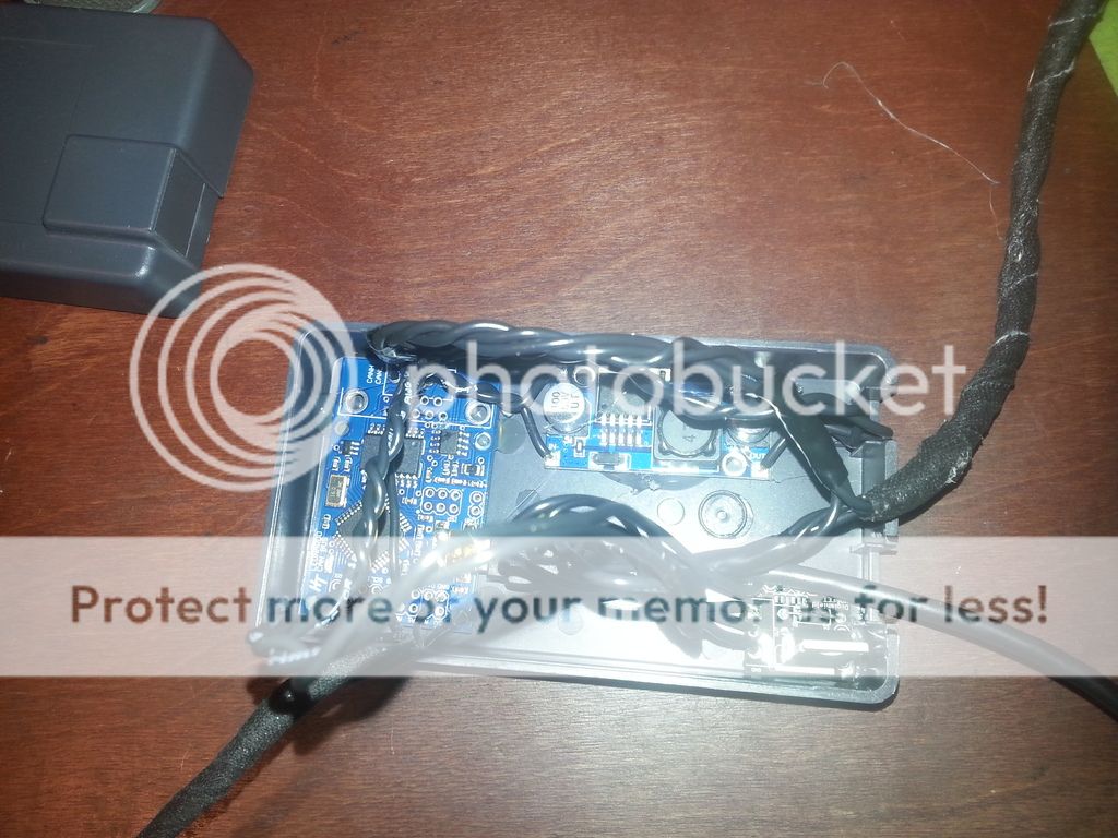
glue everything in the case..or use some tape and make sure no part will touch
now time to program the chip
download arduino software here
https://www.arduino.cc/en/Main/Software
install it
download library for the board download the zip file
https://github.com/reeedstudio/CAN_BUS_Shield
extract and insert into the arduino library folder
document/arduino/librairies and
document/arduino/arduino/librairies
you only need one but i gorgot wich one ...doh
in tools select
board:arduino leonardo
com: select the right one
and com
here is the program
/***************************************************************************
Sebastien Moreau at
s_moreau72@hotmail.com
used
Hobbytronics Leonardo CAN-BUS board
Receive Test Data and set filters on ID
Send output data via serial port
Leonardo CAN BUS product page
Leonardo CAN BUS board | L-CANBUS | HobbyTronics
Hobbytronics.co.uk
For mcp_can use this library
https://github.com/reeedstudio/CAN_BUS_Shield
download the ZIP at the right of the screen
and insert what IN the zip folder into the library
rebbot arduino software
****************************************************************************/
#include <mcp_can.h>
#include <mcp_can_dfs.h>
#include <SPI.h>
unsigned int rxId;
unsigned char rxLen = 0;
unsigned char rxBuf[8];
volatile unsigned char canData = 0;
int AcReq = LOW;
int AcInputValue = LOW;
int Pulse=0;
int AcMem = LOW;
long CommCheck1 = 0; //check if communication is working if not do a reset
long CommCheck2 = 0;
MCP_CAN CAN0(17); // Set CS to pin 17
void setup() {
// put your setup code here, to run once:
delay (250); // wait a bit
Serial.begin(9600);
CAN0.begin(CAN_500KBPS); // init can bus : baudrate = 500k
attachInterrupt(4, can_receive, FALLING); // Pin D7 is Interrupt4 on Leonardo
pinMode(6, OUTPUT); // AC request status to send to haltech
pinMode(8, INPUT_PULLUP); // AC status input to read haltech AC confirmation
pinMode(9, OUTPUT); // Variable output for AC solenoid
analogWrite(9,0);// AC solenoid to 0V
pinMode(23, OUTPUT); // Led output activation mimic AC request
delay (250); //wait a bit
// *********************************************************
// Basic Filtering on ID
// *********************************************************
// Bytes 1 and 2 of mask/filter apply to ID
// So the Mask and filter below will only allow ID 0x350 through
// ---- ID -----
CAN0.init_Mask(0, 0, 0xFFFF); // 1111 1111 1111 1111
CAN0.init_Filt(0, 0, 0x0001); // 0000 0000 0000 0001 - FAIL
CAN0.init_Filt(1, 0, 0x0001); // 0000 0000 0000 0001 - FAIL
CAN0.init_Mask(1, 0, 0xFFFF); // 1111 1111 1111 1111
CAN0.init_Filt(2, 0, 0x0001); // 0000 0000 0000 0001 - FAIL
CAN0.init_Filt(3, 0, 0x0001); // 0000 0000 0000 0001 - FAIL
CAN0.init_Filt(4, 0, 0x0350); // 0000 0011 0101 0000 - ACCEPT
CAN0.init_Filt(5, 0, 0x0001); // 0000 0000 0000 0001 - FAIL
}
void loop() {
// put your main code here, to run repeatedly:
//*****************Check if comm is operational if not do a reset***************************
++CommCheck1; //increase loop counter and check for comm fault if no comm then reset comm port
if (CommCheck1 == 200000) {
CommCheck1 = 0 ;
//if we didn't receive any message reset the port
if (CommCheck2 == 0) {
CAN0.begin(CAN_500KBPS); // reset comm port
attachInterrupt(4, can_receive, FALLING); // Pin D7 is Interrupt4 on Leonardo
// *********************************************************
// Basic Filtering on ID
// *********************************************************
// Bytes 1 and 2 of mask/filter apply to ID
// So the Mask and filter below will only allow ID 0x350 through
// ---- ID -----
CAN0.init_Mask(0, 0, 0xFFFF); // 1111 1111 1111 1111
CAN0.init_Filt(0, 0, 0x0001); // 0000 0000 0000 0001 - FAIL
CAN0.init_Filt(1, 0, 0x0001); // 0000 0000 0000 0001 - FAIL
CAN0.init_Mask(1, 0, 0xFFFF); // 1111 1111 1111 1111
CAN0.init_Filt(2, 0, 0x0001); // 0000 0000 0000 0001 - FAIL
CAN0.init_Filt(3, 0, 0x0001); // 0000 0000 0000 0001 - FAIL
CAN0.init_Filt(4, 0, 0x0350); // 0000 0011 0101 0000 - ACCEPT
CAN0.init_Filt(5, 0, 0x0001); // 0000 0000 0000 0001 - FAIL
Serial.println("Had to reset comm port, no communication!!");
}
//if we received to many message ...the filter didn't work...reset the port
else if (CommCheck2 > 1000) {
CAN0.begin(CAN_500KBPS); // reset comm port
attachInterrupt(4, can_receive, FALLING); // Pin D7 is Interrupt4 on Leonardo
// *********************************************************
// Basic Filtering on ID
// *********************************************************
// Bytes 1 and 2 of mask/filter apply to ID
// So the Mask and filter below will only allow ID 0x350 through
// ---- ID -----
CAN0.init_Mask(0, 0, 0xFFFF); // 1111 1111 1111 1111
CAN0.init_Filt(0, 0, 0x0001); // 0000 0000 0000 0001 - FAIL
CAN0.init_Filt(1, 0, 0x0001); // 0000 0000 0000 0001 - FAIL
CAN0.init_Mask(1, 0, 0xFFFF); // 1111 1111 1111 1111
CAN0.init_Filt(2, 0, 0x0001); // 0000 0000 0000 0001 - FAIL
CAN0.init_Filt(3, 0, 0x0001); // 0000 0000 0000 0001 - FAIL
CAN0.init_Filt(4, 0, 0x0350); // 0000 0011 0101 0000 - ACCEPT
CAN0.init_Filt(5, 0, 0x0001); // 0000 0000 0000 0001 - FAIL
Serial.print("Had to reset comm port, filter didn't work : ");Serial.println(CommCheck2);
CommCheck2 = 0 ;
}
//
else {
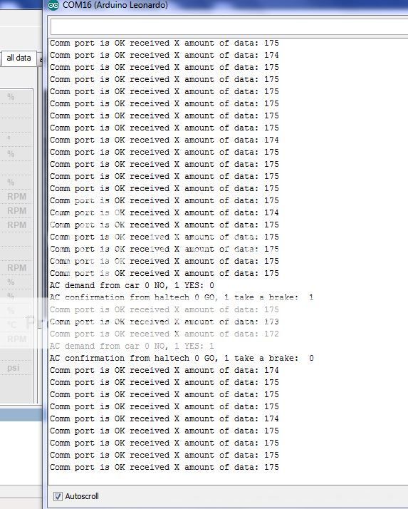
Serial.print("Comm port is OK received X amount of data: "); Serial.println(CommCheck2);
CommCheck2 = 0 ;
}
}
//*************************End of comm check*****************************************
//************************If data is received treat it********************************
if(canData)
{
canData=0;
++CommCheck2; // increase if data is receive
CAN0.readMsgBuf(&rxLen, rxBuf); // Read data: len = data length, buf = data byte(s)
rxId = CAN0.getCanId(); // Get message ID
/**
Serial.print("ID: ");
Serial.print(rxId, HEX);
Serial.print(" Data: ");
for(int i = 0; i < rxLen; i++) // Print each byte of the data
{
if(rxBuf
< 0x10) // If data byte is less than 0x10, add a leading zero
{
Serial.print("0");
}
Serial.print(rxBuf, HEX);
Serial.print(" ");
}
Serial.println();
**/
//Evaluate AC request status ON or OFF
switch (rxBuf[1]) {
case 0x10:
AcReq = LOW;
break;
case 0x18:
AcReq = LOW;
break;
case 0x58:
AcReq = LOW;
break;
case 0x1B:
AcReq = HIGH;
break;
case 0x5B:
AcReq = HIGH;
break;
}
if (AcReq != AcMem) {
AcMem = AcReq;
Serial.print("AC demand from car 0 NO, 1 YES: ");Serial.println(AcReq);
}
digitalWrite(6, AcReq);
digitalWrite(23, AcReq);
} // end if
//************************END of received data treatment***********************
//************* Read Haltech output and put AC ON or OFF accordingly************************
//*** max pulse is at 200 that give around 10V that is what i have seen on stock system***
if (AcInputValue != digitalRead(8)) {
AcInputValue = digitalRead(8);
Serial.print("AC confirmation from haltech 0 GO, 1 take a brake: ");Serial.println(AcInputValue);
if (AcInputValue == HIGH) {
for (Pulse=200 ; Pulse >=0; Pulse--){
analogWrite(9,Pulse);
delay (3);
}
}
else {
for (Pulse=0 ; Pulse <=200; Pulse++){
analogWrite(9,Pulse);
delay (10);
}
}
}
//************End of input and AC driving**********************************************
}
void can_receive()
{
// CAN Receive Interrupt
canData = 1;
}
upload it to the device...click the arrow saying upload
do a quick check
and open the serial monitor window
tool / serial monitor
you will only see that there is no comm and port is reset
this is a normal exemple when connected to car
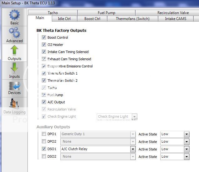
uncheck factory a/c input and program DPI1 as follow
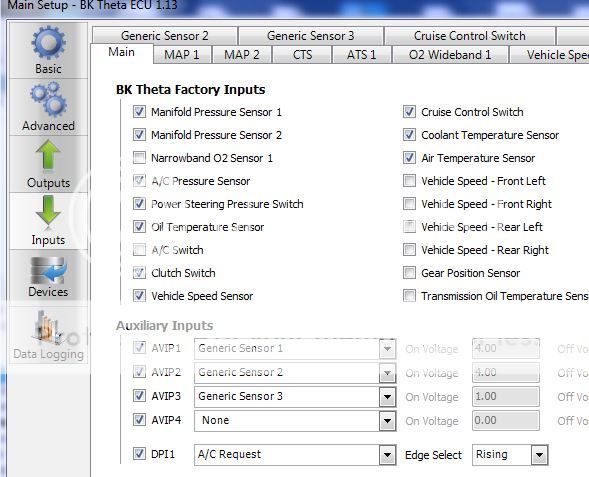
and programs DSO1 as follow