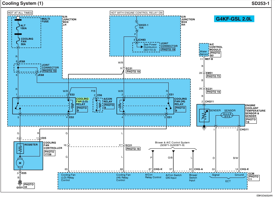

This mod enables you to control either the lo or the hi speed cooling fan, automatically or manually. It does not change OEM behavior. OEM the lo speed fan is the only one the ECU controls for coolant temp. The hi speed fan is only for AC hi pressure. The ECU will also turn the lo speed fan on when the AC is on at speeds under 30 mph.
If you have a BR tune then the lo speed fan is on all the time unless the AC is on, then it reverts back to OEM logic.
With this mod I wanted to first stop the lo speed fan from being on all the time and second to be able to manually both be able to turn on the fan with a switch and also have an adjustable temp controller turn the fan on.
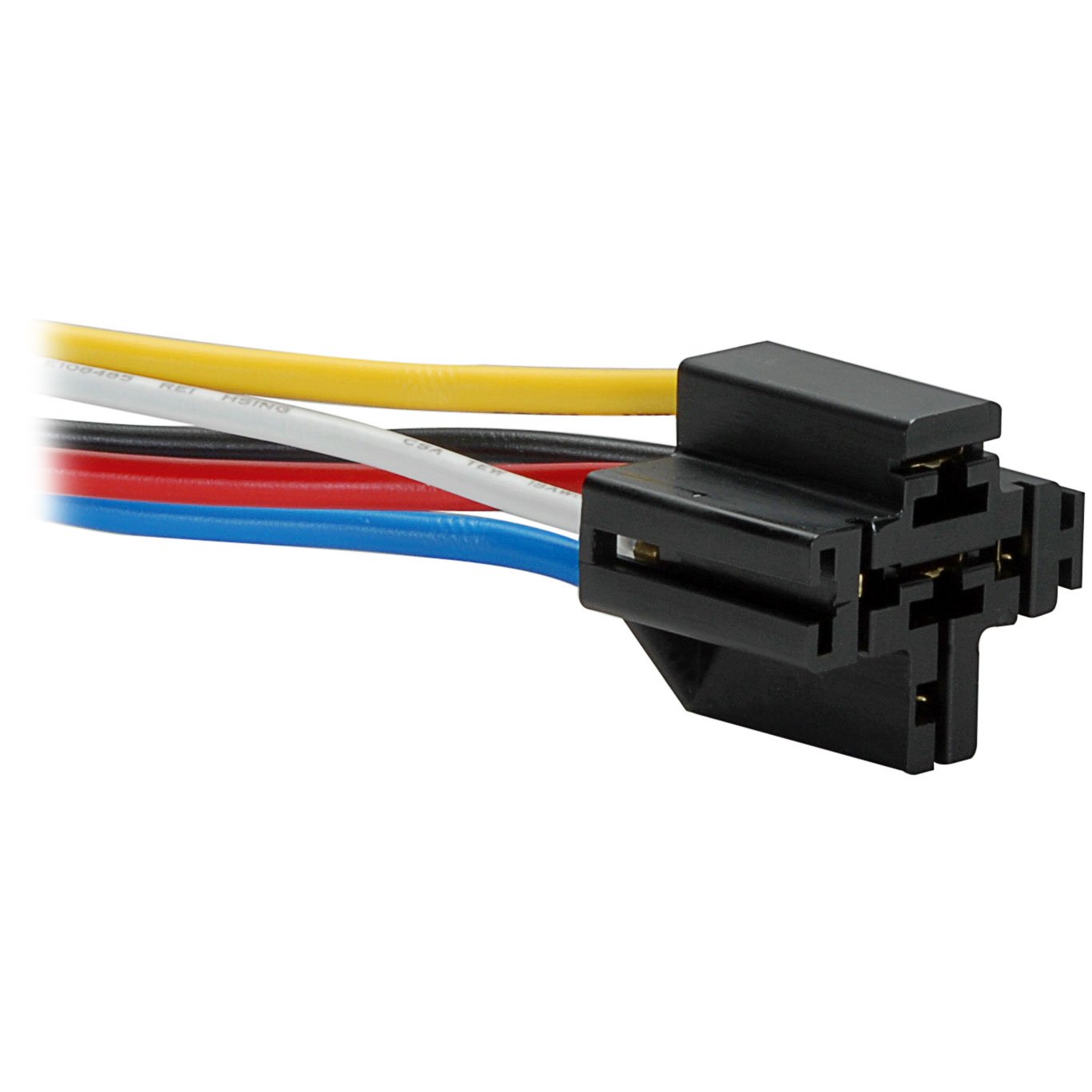
To kill the lo speed fan I pulled the lo speed fan relay out. And set the controller to turn on the hi speed fan. I leave the relay in the fuse box upside down so if there ever was a need to quickly revert back to the way it was all that needs done is put the relay back in.
The controller will turn the hi speed fan on by grounding the relay coil wire. This wire is just tapped into so there is still OEM control for the his speed fan when the AC is on. You tap in two wires, one going into the cabin for the manual switch and another for the temp controller.
What is very good about grounding the coils is you use small ga wire and no fuses are needed. There is no worry about grounding a hot 12V+ wire.
The controller is made by Derale and is stock # 16769. The probe slips under the upper radiator hose between the radiator hose outlet pipe and the hose. There is a piece of foam that allows it to seal. There is a cheaper type that has the probe put in between the fins of the radiator. This type does not work as accurately but does work.
So on to the job.
If you have a BR tune then the lo speed fan is on all the time unless the AC is on, then it reverts back to OEM logic.
With this mod I wanted to first stop the lo speed fan from being on all the time and second to be able to manually both be able to turn on the fan with a switch and also have an adjustable temp controller turn the fan on.
To kill the lo speed fan I pulled the lo speed fan relay out. And set the controller to turn on the hi speed fan. I leave the relay in the fuse box upside down so if there ever was a need to quickly revert back to the way it was all that needs done is put the relay back in.
The controller will turn the hi speed fan on by grounding the relay coil wire. This wire is just tapped into so there is still OEM control for the his speed fan when the AC is on. You tap in two wires, one going into the cabin for the manual switch and another for the temp controller.
What is very good about grounding the coils is you use small ga wire and no fuses are needed. There is no worry about grounding a hot 12V+ wire.
The controller is made by Derale and is stock # 16769. The probe slips under the upper radiator hose between the radiator hose outlet pipe and the hose. There is a piece of foam that allows it to seal. There is a cheaper type that has the probe put in between the fins of the radiator. This type does not work as accurately but does work.
So on to the job.


")